Installing ND v3.2.x on ESXI
About This Document
Section titled “About This Document”This document serves as a Method of Procedure (MoP) for installing and setting up a Nexus Dashboard node, with optional multi-node clustering instructions.
This guide targets the Unified image for Nexus Dashboard 3.2(1i) on ESXi 8.0.3.
The “Unified” image refers to the consolidated Nexus Dashboard platform (3.1+), where the App Store has been deprecated. In Unified images, instead of downloading separate images for NDFC, NDO, or NDI, these services can now be enabled from the Unified image itself, pulling the image for the specific service from the cloud for you.
Hosting Requirements
Section titled “Hosting Requirements”When deploying ND on ESXi or vCenter, you can choose between two types of nodes:
- Data Node: higher system requirements designed for specific services that require the additional resources.
- App Node: smaller resource footprint that can be used for most services.
This document will be deploying the App Node due to its lesser system requirements while also meeting future needs (NDFC deployment).
| Data Node | App Node |
|---|---|
| - VMware ESXi 7.0, 7.0.1-3, 8.0, 8.0.2 - VMware vCenter 7.0.1-3, 8.0, 8.0.2 if deploying using vCenter Each VM requires the following: - 32 vCPUs with physical reservation of at least 12,000 MHz. - 128GB of RAM with physical reservation. - 3TB SSD storage for the data volume and an additional 50GB for the system volume. The SSD must be attached to the data store directly or in JBOD mode if using a RAID Host Bus Adapter (HBA). The SSDs must be optimized for Mixed Use/Application (not Read-Optimized): - 4K Random Read IOPS: 93000 - 4K Random Write IOPS: 31000 | - VMware ESXi 7.0, 7.0.1-3, 8.0, 8.0.2 - VMware vCenter 7.0.1-3, 8.0, 8.0.2 if deploying using vCenter Each VM requires the following: - 16 vCPUs with physical reservation of at least 12,000 MHz. - 64GB of RAM with physical reservation. - 500GB HDD or SSD storage for the data volume and an additional 50GB for the system volume. Note: If you are deploying ND to for NDI past version ND 3.0(1i), you must increase the default disk of 500GB to 1536GB. |
| For more details on ESXi / VM requirements, reference Cisco Nexus Dashboard and Services Deployment and Upgrade Guide, Release 3.2.x |
Creating the VM
Section titled “Creating the VM”The following section will walkthrough the process of installing Nexus Dashboard in ESXi.
For more details, reference the official Cisco documentation at Cisco Nexus Dashboard and Services Deployment and Upgrade Guide, Release 3.2.x | Deploying Nexus Dashboard Directly in VMware ESXi.
Instructions will be indicated bellow the associated screenshot.
Downloading the ND Image
Section titled “Downloading the ND Image”Browse to the Cisco Software Download page, and navigate to “Nexus Dashboard” images.
From there, download the “nd-dk9.3.2.1i.ova” image to your local computer.
The syntax of Nexus Dashboard images is:
nd-ndk9.<version>.ova
Navigate to the VM Tab
Section titled “Navigate to the VM Tab”Log in to your ESXi Dashboard.
Navigate to the “Virtual Machines” tab on the left side-bar.
Create the VM
Section titled “Create the VM”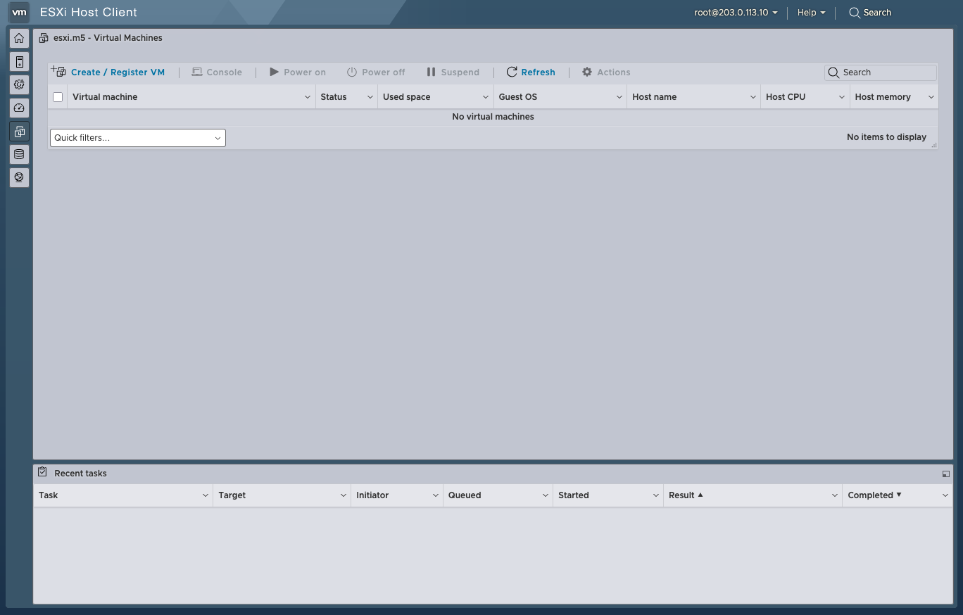
Click the “Create / Register VM” button at the to left of the main table.
Select OVA Deployment
Section titled “Select OVA Deployment”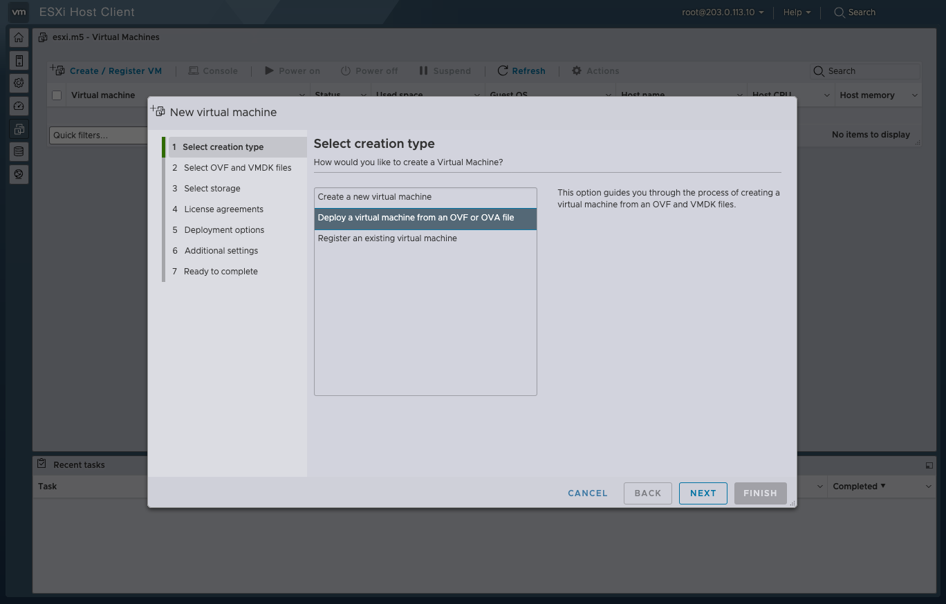
Then select the “Deploy a virtual machine from an OVF or OVA file” option. Then click the “NEXT” button at the bottom right.
Name & Upload the OVA
Section titled “Name & Upload the OVA”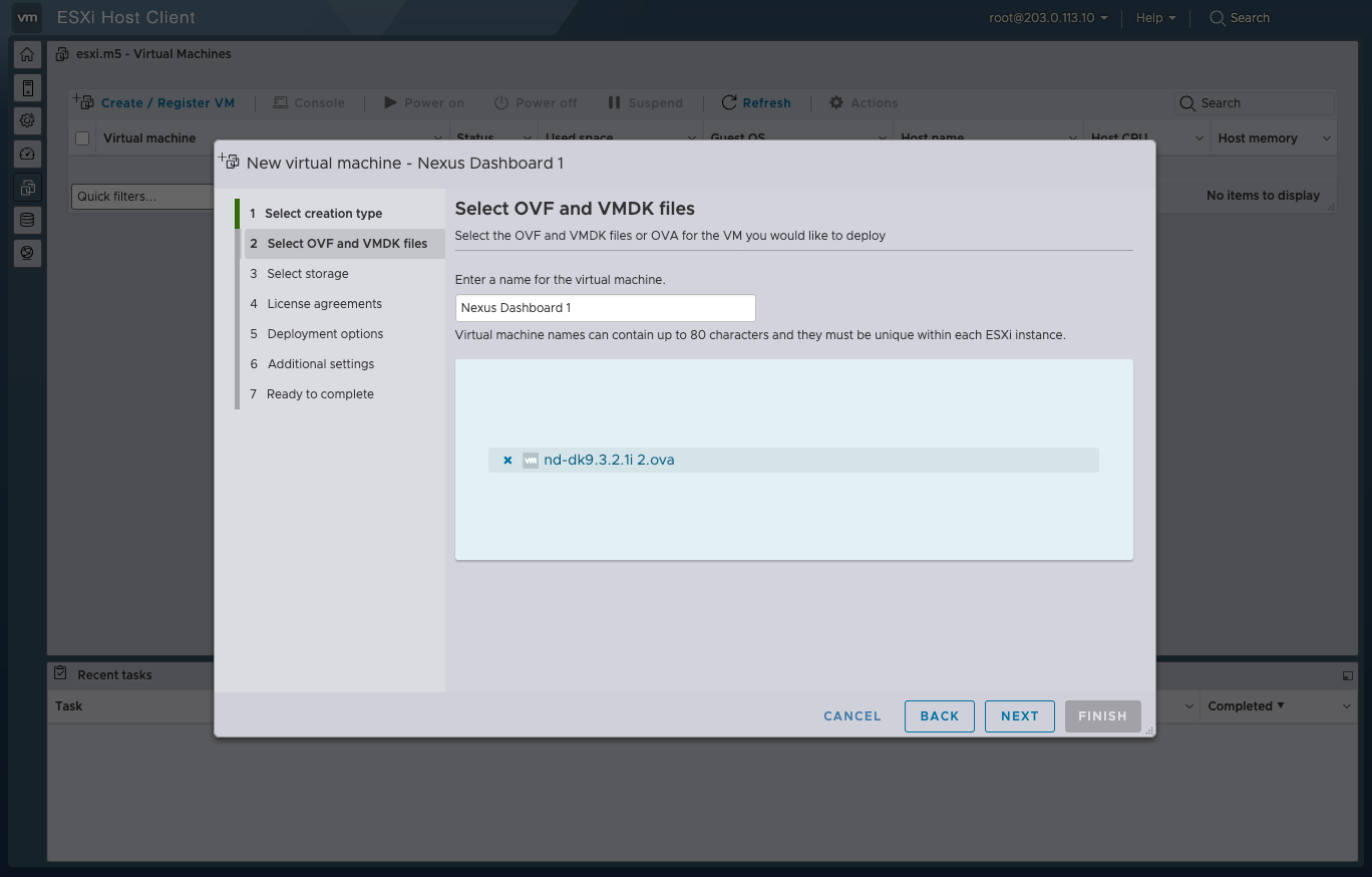
Enter the name of your VM in the name field. This document will cover clustering, so the names will be numbered.
Click into the “Click to select files or drag/drop” field to upload the OVA file.
Then click the “NEXT” button at the bottom right.
Select ESXi Datastore
Section titled “Select ESXi Datastore”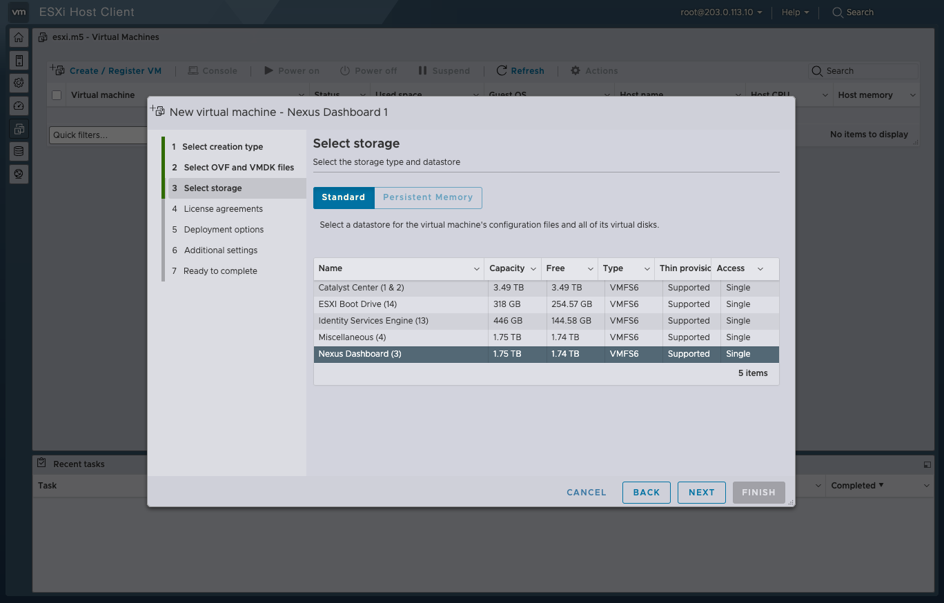
Select which Datastore you want to use for your ND node.
Remember that the App Node deployment storage requirements are as follows:
500GB HDD or SSD storage for the data volume and an additional 50GB for the system volume.
Then click the “NEXT” button at the bottom right.
Customize the Deployment
Section titled “Customize the Deployment”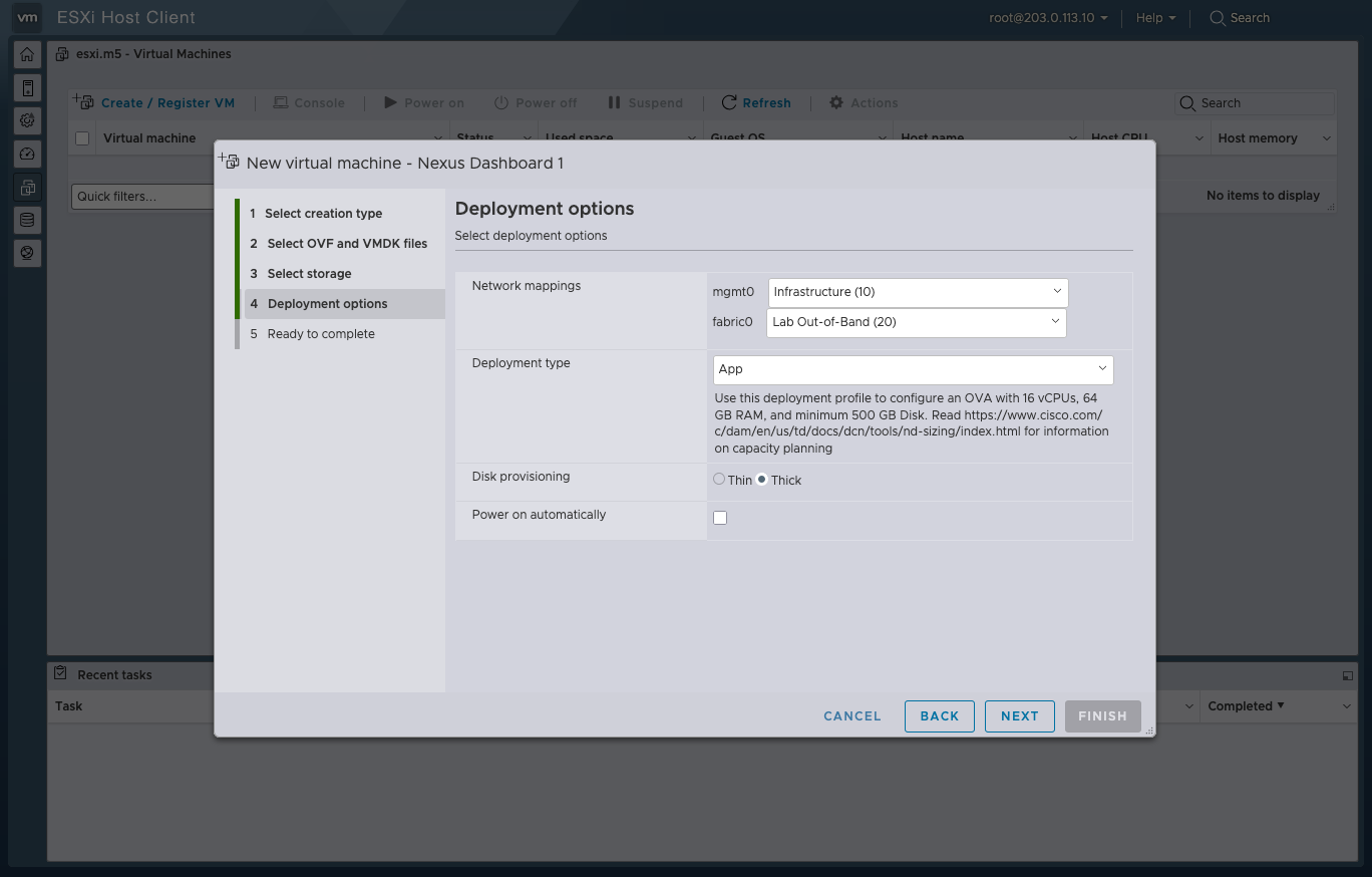
From this screen you can select 4 key options which do the following:
| Option | Guidance |
|---|---|
| Network mappings | ND nodes have 2 network interfaces, “mgmt0” and “fabric0”. Mgmt0 is used for fabric discovery by default but CAN be changed to Fabric0. The mgmt0 interface is used to host the user interface of ND (https). |
| Deployment type | Select either “Data” or “App”, explained in the above section. |
| Disk provisioning | Select either “Thin” or “Thick”, but Thick is advised. |
For this MOPs environment, the network, Infrastructure (10) is used exclusively for OOB management plane traffic (ESXi gui, ND gui, ISE gui) (non-destructive), whereas Lab Out-of-Band (20) is used for connecting lab devices’ mgmt0 interfaces, acting as a sudo in-band out-of-band network, that can be destructive, as NDFC will interact with them.
Uncheck the “Power on automatically” field, so that the vApp & vmdk can have time to download, and the VM does not power up unexpectedly.
Then click the “NEXT” button at the bottom right.
Confirm VM Specs
Section titled “Confirm VM Specs”Once all the details look correct, click the “FINISH” button at the bottom right.
VApp & VMDK Download
Section titled “VApp & VMDK Download”Now that the VM is created, this will trigger the VM to automatically pull the VApp & VMDK, which can be viewed in the “Recent Tasks” tab at the bottom of the ESXi Dashboard.
Make sure to keep your ESXi session active while these files get pulled from the uploaded OVA to ensure a reliable upload.
Once the Recent Tasks for the VApp & VMDK say “Completed Successfully”, you can proceed to power on the VM.
First-Boot Setup
Section titled “First-Boot Setup”Once the VM is up and running, click on the ESXi console viewer to see the console output.
You will be prompted to run the first-time setup utility:
[ OK ] Started atomix-boot-setup.       Starting Initial cloud-init job (pre-networking)...       Starting logrotate...       Starting logwatch...       Starting keyhole...[ OK ] Started keyhole.[ OK ] Started logrotate.[ OK ] Started logwatch.
Press any key to run first-boot setup on this console...
Click the enter key.
Admin Password:Reenter Admin Password:Then confirm the admin password.
This password will be used for the
rescue-userSSH login as well as the initial GUI password.
Management Network: IP Address/Mask: 203.0.113.20/24 Gateway: 203.0.113.1Enter the management network information.
Is this the cluster leader?: yFor the first node only, designate it as the “Cluster Leader”.
You will log into the cluster leader node to finish configuration and complete cluster creation.
Please review the configManagement network:  Gateway: 203.0.113.1  IP Address/Mask: 203.0.113.20/24Cluster leader: no
Re-enter config? (y/N): N
You will be asked if you want to change the entered information. If all the fields are correct, choose N to proceed. If you want to change any of the entered information, enter y to re-start the basic configuration script.
At this point, if you are spinning up a cluster of ND nodes, you should get all nodes to this point. NOTE: All nodes need the same admin password, and only one can be the leader.
Once indicated from the console that the setup is complete, it will prove the URL to get to the GUI: https://<node-mgmt-ip>
Cluster Bringup
Section titled “Cluster Bringup”The rest of the configuration workflow takes place from one of the node’s GUI. You can choose any one of the nodes you deployed to begin the bootstrap process and you do not need to log in to or configure the other two nodes directly.
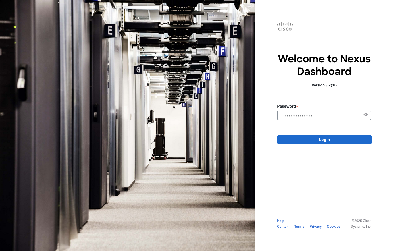
Enter the password you provided during the First-Boot Setup step and click Login.
Configuration
Section titled “Configuration”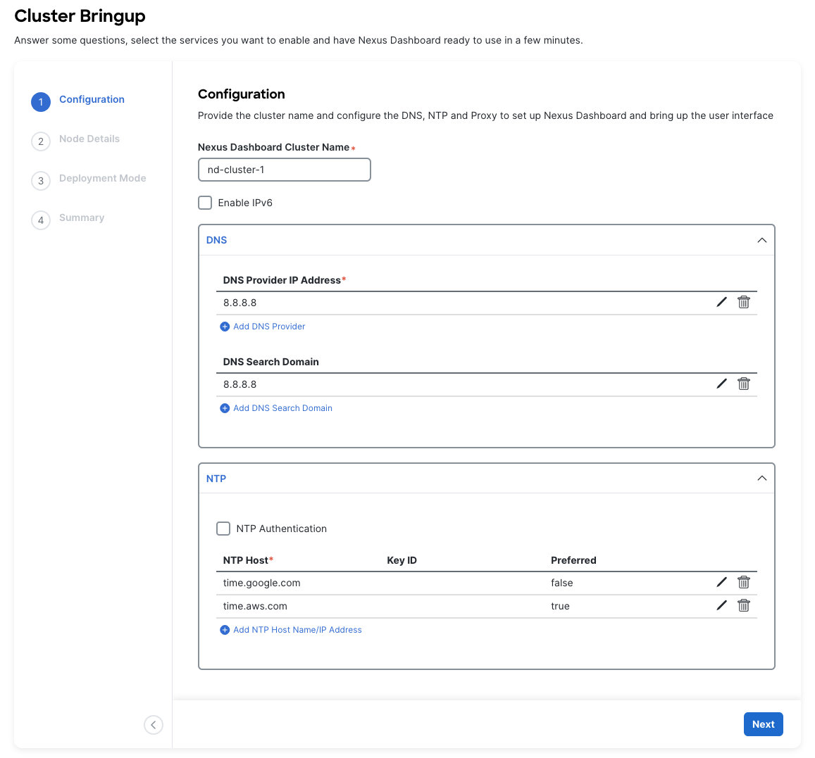
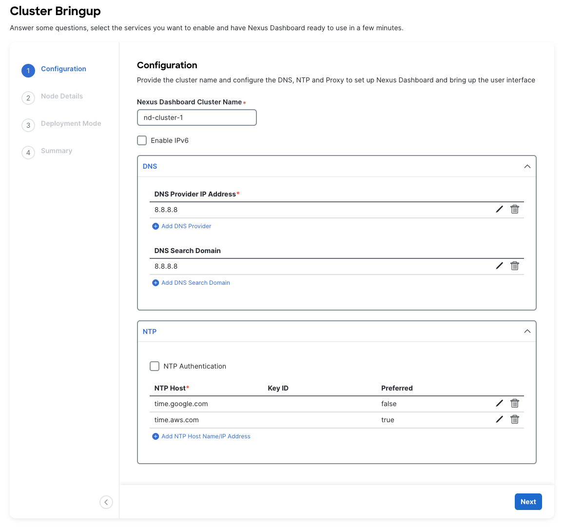
The first section “Configuration” allows the user to configure key node details.
| Section | Guidance |
|---|---|
| Nexus Dashboard Cluster Name | This will be the name of your ND cluster. The name should be unique across all clusters, if applicable. |
| DNS | Provide one or many IP addresses for the following: - DNS Provider - DNS Search Domain |
| NTP | Provide one or many IP addresses for the nodes NTP servers. Ensure that you enter multiple from various providers. ND will loose functionality if it’s NTP servers are lost. |
| Proxy | If you have an HTTP/HTTPS proxy, configure it here. If you are not using a proxy, you have to select Skip Proxy. |
| Advances Settings | More below. |
| For the Advanced Settings: |
- The application overlay network defines the address space used by the application’s services running in the Nexus Dashboard. The field is pre-populated with the default
172.17.0.1/16value. - The services network is an internal network used by the Nexus Dashboard and its processes. The field is pre-populated with the default
100.80.0.0/16value. - Make sure that these do not collide with your existing infra networks.
Once complete, click the “Next” button at the bottom right.
Node Details
Section titled “Node Details”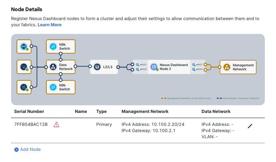
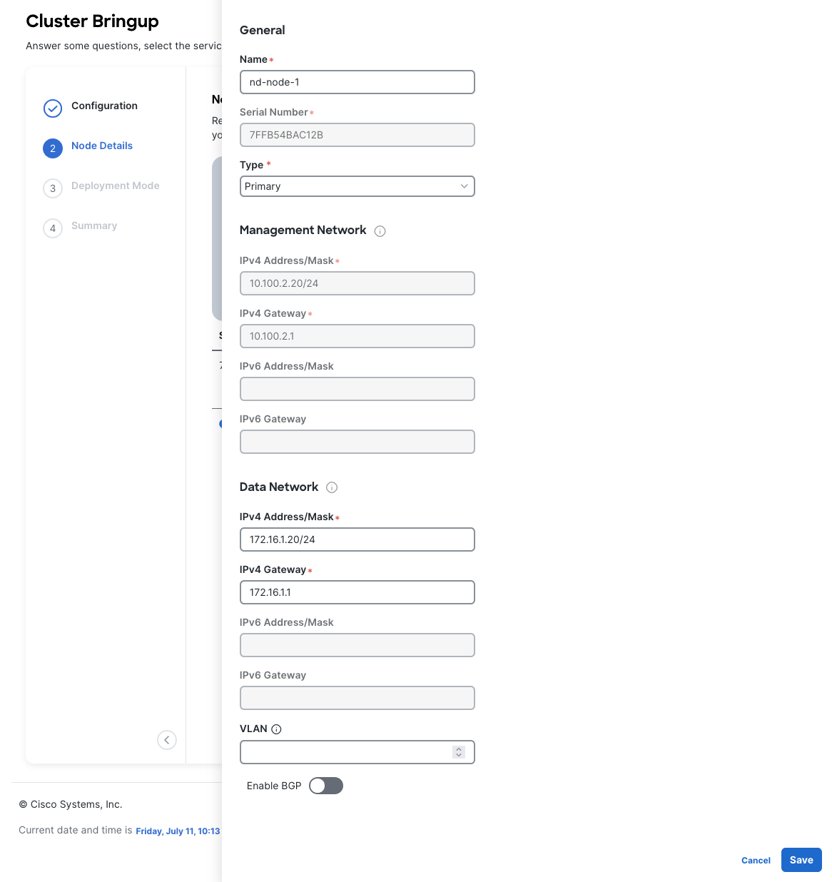
Enter the name of the local node in the Name field. Note that this must be unique within the cluster.
You have already defined the Management network and IP address for the node into which you are currently logged in during the initial node configuration in earlier steps, but you must also provide the Data network information for the node before you can proceed with adding the other nodes and creating the cluster.
For this MOP, the Data network will be 172.16.1.0/24, as this network will later be configured to discover switches, which also live on that network.
If you are clustering nodes, log into the main node GUI, then add more nodes in this section. Note that the Type field should be the same across all nodes in your cluster (use Primary for a single node or cluster setup). If you are setting up a cluster that will be added to multi-clustering, you can set it to Secondary or Standby.
Once complete, click the “Next” button at the bottom right.
Deployment Mode
Section titled “Deployment Mode”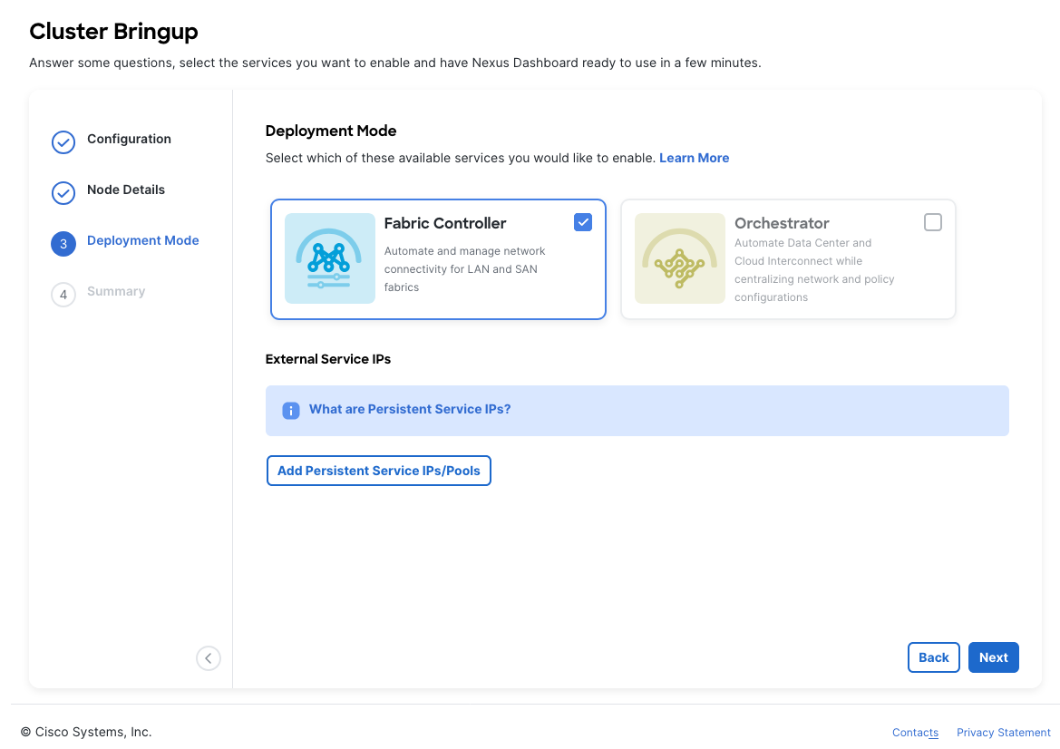
Select which Deployment Modes you intend to run on this ND node. Note that the Deployment Mode for all nodes within a cluster must match.
Depending on the number of nodes in the cluster, some services or cohosting scenarios may not be supported.
The deployment mode cannot be changed after the cluster is deployed, so you must ensure that you have completed all service-specific prerequisites are met.
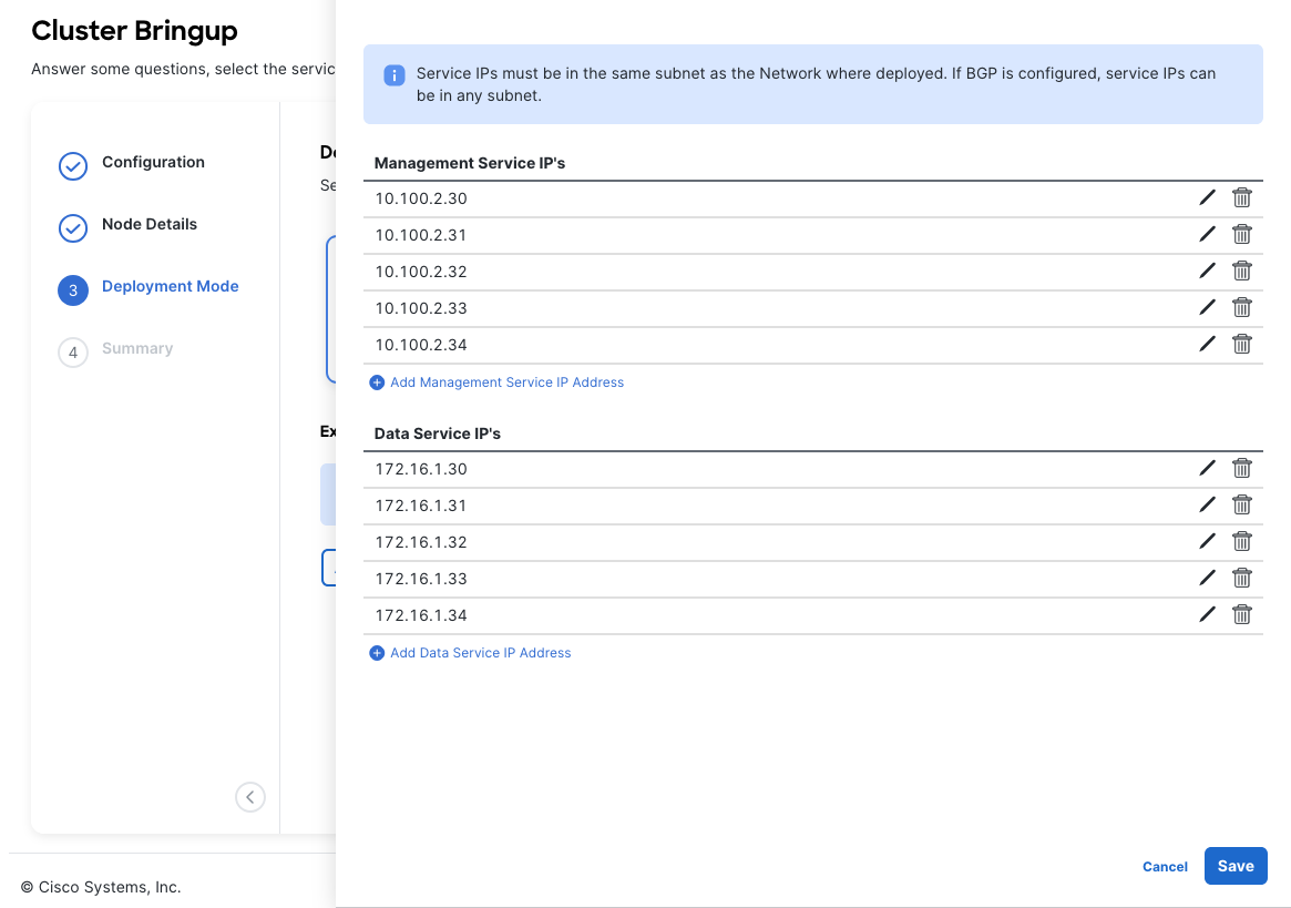
If you chose a deployment mode that includes Fabric Controller or Insights, click Add Persistent Service IPs/Pools to provide one or more persistent IPs required by Insights or Fabric Controller services. These IPs will be used for various sub-servcies within these programs.
Some of these services include “cisco-ndfc-dcnm-syslog-trap-data” or “cisco-ndfc-dcnm-poap-data-http-ssh” which are sub services that clients will target.
Once complete, click the “Next” button at the bottom right.
Summary & Bootstrap
Section titled “Summary & Bootstrap”In the Summary screen, review and verify the configuration information, click Save, and click Continue to confirm the correct deployment mode and proceed with building the cluster.
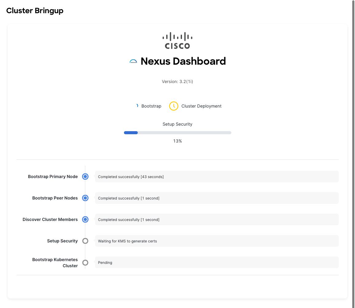
It may take up to 30 minutes for the cluster to form and all the services to start. When cluster configuration is complete, the page will reload to the Nexus Dashboard GUI.
Note that the GUI may log out or refresh multiple times throughout the bootstrapping process.
Wrap Up
Section titled “Wrap Up”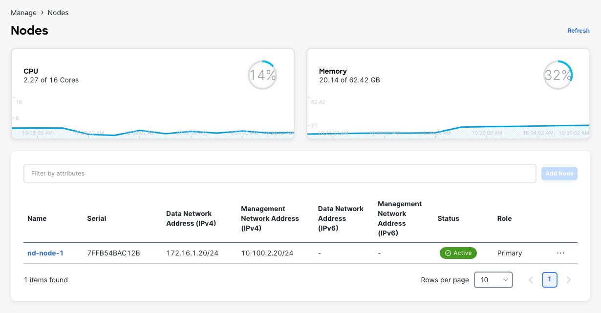
Once the bootstrapping process completes, you should see in the Manage > Nodes tab that the node is Healthy, and all other nodes (if clustered) are also present and Healthy.
This concludes the MOP.
For next steps, check out [[Getting Started with NDFC]].