Spanning Tree Protocol (STP)
For an intro to 802.1D Spanning-Tree, checkout CertBros Explanation for an excellent conceptual start.
Remember, like most Layer 2 protocols, LOWER values are better!
Keep in mind that 802.1D Spanning-Tree is only ever implemented on modern network switches using PVST+. This enhancements allows a spanning-tree instance to run per VLAN. This means that each VLAN has its own spanning-tree process and topology— but devices can only handle up to 128 instances.
Most of this document is focused on PVST+ spanning-tree operation, with a section for Rapid-PVST+ for [[Rapid Spanning-Tree Protocol (RSTP)]] operations at the end. A separate document will be made for [[Multiple Spanning-Tree (MST)]].
BPDUs and Costs
Section titled “BPDUs and Costs”BPDUs are special Layer 2 messages forwarded by switches downstream to share STP information. These messages are used to:
- Elect the Root Bridge
- Determine the best path to the Root
- Prevent loops by defining port roles
There are two main types:
| Type | Description |
|---|---|
| Configuration | Used in standard STP for root election and updates. |
| Topology Change Notification (TCN) | Alerts the network of a topology change. |
The “best path” is what is called a Path Cost, or a Root Cost.
- Each switch adds its the receiving ports cost to the cost received in a BPDU.
- For example, if a non-root switch receives a BPDU from the root bridge with a cost of 0, it will then look at the received interfaces bandwidth, and add that equivalency value to the root cost when forwarding it downstream.
- It then forwards the BPDU with the updated root cost to other switches.
- Each switch uses this info to:
- Choose the Root Port (best path to Root Bridge)
- Elect Designated Ports on each segment
Port Cost is a numerical value assigned to each interface based on its bandwidth, used by STP to select the lowest-cost path to the Root Bridge.
There are two path cost calculation methods:
| Link Bandwidth | (Short) Cost | (Long) Cost |
|---|---|---|
| 10 Mbps | 100 | 2,000,000 |
| 100 Mbps | 19 | 200,000 |
| 1 Gbps | 4 | 20,000 |
| 10 Gbps | 2 | 2,000 |
| 100 Gbps | N/A | 200 |
| 1 Tbps | N/A | 20 |
Configuring Costs
Section titled “Configuring Costs”Use the following configuration to use the Long port costs:
spanning-tree pathcost method longUse the following configuration to custom configure a port cost for an interface:
spanning-tree cost <1-200000000>spanning-tree vlan 1 cost <1-200000000>Note: if you do not specify which VLAN, it will apply to all VLANs on that interface.
Root Bridge Election
Section titled “Root Bridge Election”Devices running STP will first negotiate and determine who the Root Bridge is in the network. To do this, they perform the following steps:
-
All switches assume they are the Root Bridge initially. Each switch sends out BPDUs containing its own Bridge ID (
Bridge Priority (default is 32768) + VLAN ID + ":" + MAC Address). -
As switches receive BPDUs from other switches, they compare them to their current best-known BPDU (themselves if first received). If a switch receives a superior BPDU (one with a lower Bridge ID), it stops claiming to be root and forwards that superior BPDU instead. Note that when forwarding it alters values like root costs etc.
-
Eventually, all switches agree on the same root bridge, the switch with the lowest Bridge ID.
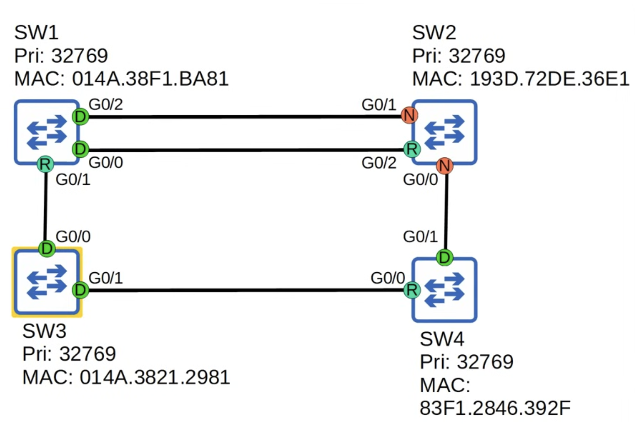
For example, in the following topology, SW2 has the lowest MAC address, which is appended to the Bridge Priority, so it becomes the Root Bridge.
| Switch | Priority | MAC Address | Bridge ID |
|---|---|---|---|
| SW1 | 32768 | 00:11:22:33:44:03 | 32768.00:11:22:33:44:03 |
| SW2 | 32768 | 00:11:22:33:44:01 | 32768.00:11:22:33:44:01 ← 🏆 |
| SW3 | 32768 | 00:11:22:33:44:02 | 32768.00:11:22:33:44:02 |
Configuring the Root Bridge
Section titled “Configuring the Root Bridge”Spanning-tree priority values can only be configured in increments of 4096. Making its configurable range to be 0-61440.
(config)#spanning-tree vlan 1 priority ?% Bridge Priority must be in increments of 4096.% Allowed values are: 0 4096 8192 12288 16384 20480 24576 28672 32768 36864 40960 45056 49152 53248 57344 61440There are three ways to configure a devices spanning-tree priority:
(config)# spanning-tree vlan 1 priority 4096(config)# spanning-tree vlan 1 root primary(config)# spanning-tree vlan 1 root secondaryThe command that uses root primary will take the current known Root Bridge’s priority, and set its own priority to TWO intervals less than, so: mypriority - 8192.
The command that uses root secondary will take the current known Root Bridge’s priority, and set its own priority to ONE intervals less than, so: mypiority - 4096.
Port Elections
Section titled “Port Elections”All ports on the Root Bridge are Designated ports (forwarding state).
Each remaining switch will select ONE of its interfaces to be its Root Port (forwarding state).
Selection: Root Ports
Section titled “Selection: Root Ports”The Root Port Selection process is as follows:
- Lowest Root Cost - BUT what if they have the same Root Cost?
- Lowest neighbor Bridge ID - BUT what if they have the the Bridge ID (two ports to the same switch)?
- Lowest neighbor Port ID
- The Port ID is a value assigned to all ports, with a numerical value per port as the decimal:
Port Priority (128) + "." + Port Number.
Selection: Blocking Ports
Section titled “Selection: Blocking Ports”Each remaining collision domain will select ONE interface to be a Designated Port (forwarding state). The other port in the collision domain will be Blocking (**non-designated).
The Blocking Selection process is as follows:
- LOCAL interface with lowest Root Cost - becomes Designated and the neighbor Blocks.
- BUT what if its a tie?
- LOCAL switch with the lowest Bridge ID - becomes Designated and the neighbor Blocks.
Below is an excellent example of this election process from Jeremy’s IT Lab - Part 1 (30 minutes in).
Understanding Timers
Section titled “Understanding Timers”The general flow of an 802.1D STP environment in terms of timers is as follows:
- Failure Occurs
- Max Age (20s) — Wait to detect failure.
- Forward Delay (15s) — Listening…
- Forward Delay (15s) — Learning…
- Port becomes Forwarding
| Timer | Default | Used By |
|---|---|---|
| Hello | 2 seconds | Root Bridge |
| Forward Delay | 15 seconds | All Bridges |
| Max Age | 20 seconds | All Non-Root Bridges |
! STP & RSTP(config)# spanning-tree vlan 1 hello-time <1-10>(config)# spanning-tree vlan 1 max-age <6-40>(config)# spanning-tree vlan 1 forward-time <4-30>
! RSTP(config)# spanning-tree mode rapid-pvst(config)# interface Ethernet1/1(config-if)# spanning-tree link-type point-to-point
Resources
Section titled “Resources”CertBros Explanation CBT Micro-Nugget Jeremy’s IT Lab - Part 1 Jeremy’s IT Lab - Part 2 Jeremy’s IT Lab - Algorithm Jeremy’s IT Lab - Analyzing CBT Nuggets - CCIE L2 Cisco Press STP Whitepaper INE Course - Switched Campus Kevin Wallace - Deep Dive