EIGRP (Enhanced Interior Gateway Routing Protocol)
Protocol Structure
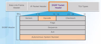
Section titled “Protocol Structure”Protocol number 88.
Lives inside the payload of the Layer 3 IP field.
- UPDATE: make my own diagram and explain better where it is and apacket structure
Neighborship
Section titled “Neighborship”For a neighborship to be formed, the following must match between routers:
- Must have the same AS number
- Must have the same K values
- Must have the same authentication
Messages
Section titled “Messages”RTP (Reliable Transport Protocol) is a built in message handing system to reliably deliver messages to their destinations.
- Can be modified on a per message basis to:
- Require an ACK response
- Not require an ACK response
- Used for…
- All message types!
- Hello and ACK packets DO NOT require an ACK message.
- Update, Query, and Reply DO require an ACK message
- NOTE: This is not an actual transport mechanism like at layer 4. This is built in logic on routers for EIGRP such that it can be used to handle the EIGRP messages per Cisco’s standards.
EIGRP Hello (opcode 5) messages are sent via Multicast 224.0.0.10 and use the following timers:
- Hello timer: 5 seconds
- Hold timer: 3x hello timer (15 seconds)
EIGRP Update (opcode 1) messages are sent Unicast to neighbors when:
- When a new neighbor is discovered, the EIGRP topology is exchanged
- Partial updates are sent immediately upon topology changes like:
- Link failure
- Metric change
- New networks
EIGRP Query (opcode 3) messages are sent via…
- By default, queries are sent over Multicast 224.0.0.10.
- If a known neighbor does not respond, it will Unicast it to the neighbor to confirm.
- Sent when…
- Router looses its successor for a route, and has no feasible successors (aka must be recomputed by DUAL). The route then changes from Passive to Active state.
EIGRP Reply (opcode 4) messages are sent via Unicast in response to a Query message with the requested information.
Classic vs Named
Section titled “Classic vs Named”The primary difference between EIGRP Classic and Named mode is that Classic mode uses a fragmented configuration spread across global and interface modes, while Named mode consolidates all EIGRP settings into a single, hierarchical structure.
Classic Mode
Section titled “Classic Mode”Uses 32-bit metrics.
interface GigabitEthernet0/0  ip address 192.168.1.1 255.255.255.0  ip hello-interval eigrp 1 2  ip hold-time eigrp 1 6
router eigrp 1  router-id 1.1.1.1  passive-interface GigabitEthernet0/0  network 192.168.1.0 0.0.0.255  bfd all-interfaces  no bfd interface GigabitEthernet0/0
The ip hello-interval eigrp [as] [seconds] and ip hold-time eigrp [as] [seconds] commands are used on an interface config level to change the timers for a specific autonomous-system.
The router-id [ip] command uniquely identifies a router within an EIGRP autonomous system. This ID is selected based on:
- Manually configured.
- Highest IP address on an active loopback interface.
- Highest IP address on an active physical interface.
The network [network] [wildcard] command does the following:
- Enables EIGRP on interfaces that match the subnet.
- Therefor will advertise this subnet to neighbors.
The passive-interface [interface] command is used to target an interface that already has EIGRP enabled, but specifically makes it so that the interface does not participate in EIGRP in any messaging capacity. This is used for host-only LAN interfaces like DFGWs when no EIGRP neighbors are reachable via that LAN.
The bfd all-interfaces and bfd interface [interface] commands can be used to enable BFD for EIGRP on all or target interfaces.
You can migrate a Classic Mode configuration to Named Mode with:
router eigrp 1 eigrp upgrade-cli [name]Named Mode
Section titled “Named Mode”Uses 64-bit metrics.
router eigrp NAME address-family ipv4 unicast autonomous-system 1 eigrp router-id 1.1.1.1 network 192.168.1.0 0.0.0.255 af-interface default hello-interval 2 hold-time 6 bfd af-interface GigabitEthernet0/0 passive-interface exit-address-familyThe eigrp router-id [ip] command functions the same as in Classic mode, just slightly different syntax, with needing eigrp added to the front of it.
The network [network] [wildcard] command functions the same as in Classic mode.
The hello-interval [seconds] and hold-time [seconds] commands functions the same as in Classic mode, but are applied differently. Due to the hierarchical structure of Named mode, you can apply them under any af-interface whether that be default of targeted.
The bfd command functions the same as in Classic mode, but is applied differently. Due to the hierarchical structure of Named mode, you can apply it under any af-interface whether that be default of targeted.
The passive-interface [interface] command functions the same as in Classic mode, but is applied differently. Due to the hierarchical structure of Named mode, you can apply it under any af-interface whether that be default of targeted.
Metric Calculations
Section titled “Metric Calculations”What is Delay (DLY)
Section titled “What is Delay (DLY)”This value is purely an administrative value, and DOES NOT have any affect on the interface it is configured on. The point of this value is for manual influence over path selection and metric calculation in EIGRP, IS-IS, and SR-TE.
Delay is measured in microseconds (usec).
See the below snippet of show interface GigabitEthernet1 to see the delay value:
R1# show interface GigabitEthernet1GigabitEthernet1 is up, line protocol is up Hardware is vNIC, address is 5254.00be.f048 (bia 5254.00be.f048) Internet address is 10.0.2.1/24 MTU 1500 bytes, BW 1000000 Kbit/sec, DLY 10 usec, reliability 255/255, txload 1/255, rxload 1/255When configuring Delay on an interface, you have to configure it in tens of microseconds, so if you wanted a delay of 10 (default on 1g interfaces) you would configure delay 1 on the interface:
R1(config)# interface GigabitEthernet1R1(config-if)# delay 1
R1# show interface GigabitEthernet1 | include DLY  MTU 1500 bytes, BW 1000000 Kbit/sec, DLY 10 usec,
R1# show running-config interface GigabitEthernet1interface GigabitEthernet1  delay 1
Notice: The value in the running-config is the same as the user configures.
What is Bandwidth (BW)
Section titled “What is Bandwidth (BW)”In general networking, bandwidth is the maximum rate at which data can be transferred over a specific path or interface.
See the below snippet of show interface GigabitEthernet1 to see the bandwidth value:
R1# show interface GigabitEthernet1GigabitEthernet1 is up, line protocol is up Hardware is vNIC, address is 5254.00be.f048 (bia 5254.00be.f048) Internet address is 10.0.2.1/24 MTU 1500 bytes, BW 1000000 Kbit/sec, DLY 10 usec, reliability 255/255, txload 1/255, rxload 1/255Computing BW and DLY for EIGRP
Section titled “Computing BW and DLY for EIGRP”When considering BW and DLY in EIGRP, you look at the cumulative delay from ingress and the minimum bandwidth along the entire path to the destination network.
For calculating Delay:
- Find the destination route on your topology.
- Identify every ingress interface in the path of EIGRP-enabled interfaces from the destination route (not including the interface with the IP address on it) to the router.
- Find it’s DLY value with the
show interface [interface]command.
- Find it’s DLY value with the
- Add all of the DLY values together.
For calculating Bandwidth:
- Identify every interface (ingress and egress) in the path of EIGRP-enabled interfaces from the destination route to the router.
- Find the lowest BW value with the
show interface [interface]command in Kbps.
NOTE: Further computing will happen to these values before getting put into the formula, depending which one is used later on, but none relate to the topology.
What are the rest?
Section titled “What are the rest?”TODO
K Values
Section titled “K Values”In EIGRP, K values are weighting constants (multipliers) used in the composite metric formula to determine how much importance to give to different interface attributes like bandwidth, delay, load, and reliability. They act like “knobs” that can enable, disable, or scale specific components of the routing calculation.
These K variables have two kind of associated functions:
- On/Off Logic
- Corresponding Path Attribute
On/Off Logic
Section titled “On/Off Logic”Each K value can be set to either 0 or 1.
- If it is set to 0, the Corresponding Path Attribute will NOT be used in the composite metric formula, by multiplying it by 0.
- If it is set to 1, the Corresponding Path Attribute WILL be used in the composite metric formula, by multiplying it by 1.
This essentially makes it so that you can enable or disable Corresponding Path Attributes.
By default, only K1 and K3 are enabled (1). Meaning only BW and DLY are used in the composite metric formula.
Configuring On/Off Status
The metric weights [TOS] [K1] [K2] [K3] [K4] [K5] command is used to customize the K-values On/Off status. The K1 and K3 values are 1 by default.
NOTE: The TOS field must always be set to 0.
router eigrp 1 metric weights 0 1 0 1 0 1router eigrp NAMED address-family ipv4 unicast autonomous-system 1 metric weights 0 1 0 1 0 1NOTE: For a neighborship to form, the K values have to have the same K values enabled.
Corresponding Path Attributes
Section titled “Corresponding Path Attributes”Each K value ALSO corresponds to a specific path attribute, where if On/Off will enable or disable the following:
- K1: Bandwidth (BW)
- K2: Load
- K3: Delay (DLY)
- K4: Reliability
- K5: Reliability scaling
- K6: Extended attributes (wide metric only)
These are the values that will be multiplied by either 0 or 1 depending on their On/Off status, described in the above section.
Composite Metric Formula
Section titled “Composite Metric Formula”Classic Metric
Section titled “Classic Metric”Before plugging any values into the EIGRP Classic Metric Formula, we need to first scale the BW and DLY values such that the formula will not break due to edge cases. Note that the router will perform this scaling automatically.
- Scaled BW:
10,000,000 / BW - Scaled DLY:
DLY / 10
Now that we have scaled BW and DLY, moving forward when talking about BW or DLY it means the post-scaled version.
The following are the EIGRP Classic Metric Formulas:
$$ \text{Metric} = 256 \times \left( K_1 \cdot \text{BW} + \frac{K_2 \cdot \text{BW}}{256 - \text{Load}} + K_3 \cdot \text{Delay} \right) \times \left( \frac{K_5}{K_4 + \text{Reliability}} \right) $$
$$ \text{Metric} = 256 \times \left( K_1 \cdot \frac{10^7}{\text{BW}} + \frac{K_2 \cdot \frac{10^7}{\text{BW}}}{256 - \text{Load}} + K_3 \cdot \frac{\text{DLY}}{10} \right) \times \left( \frac{K_5}{K_4 + \text{Reliability}} \right) $$
By default the K1 and K3 values are the only ones in an On state with the value of 1. The following is what the EIGRP Classic Metric Formula equals with the default K values applies:
$$ \text{Metric} = 256 \times \left( \text{BW} + \text{Delay} \right) $$
$$ \text{Metric} = 256 \times \left( \frac{10,000,000}{\text{BW}} + \frac{\text{DLY}}{10} \right) $$
Wide Metric
Section titled “Wide Metric”The Wide Metric (used in EIGRP Named Mode) introduces a 64-bit calculation to support interfaces faster than 1Gbps.
Summary What is different from Classic Metric?
- The final multiplier of
256is now65,536 - When scaling DLY, it’s now
DLY / 1,000,000 - Terminology changes:
- BW becomes Throughput
- Delay becomes Latency
- New K Value: K6 which is
0by default. - The final composite metric calculated is
/ 128for the RIB to fit it.
$$ \text{Metric} = 65,536 \times \left( K_1 \cdot \text{Throughput} + \frac{K_2 \cdot \text{BW}}{256 - \text{Load}} + K_3 \cdot \text{Latency} + {K_6} \cdot \text{Extended} \right) \times \left( \frac{K_5}{K_4 + \text{Reliability}} \right) $$
$$ \text{Metric} = 65,536 \times \left( K_1 \cdot \frac{10^7}{\text{Throughput}} + \frac{K_2 \cdot \frac{10^7}{\text{Throughput}}}{256 - \text{Load}} + K_3 \cdot \frac{\text{Latency}}{1,000,000} + K_6 \cdot \text{Extended} \right) \times \left( \frac{K_5}{K_4 + \text{Reliability}} \right) $$
By default the K1 and K3 values are the only ones in an On state with the value of 1. The new K6 value defaults to 0. The following is what the EIGRP Wide Metric Formula equals with the default K values applied:
$$ \text{Metric} = 65,536 \times \left( \text{Throughput} + \text{Latency} \right) $$
$$ \text{Metric} = 65,536 \times \left( \frac{10,000,000}{\text{Throughput}} + \frac{\text{Latency}}{1,000,000} \right) $$
When using Wide mode, the final result is too long for the RIB, so before adding it it will Metric / 128, but will use the original for all EIGRP processes. That’s the default, but the metric rib-scale command allows values from 1 to 255 INE, and sometimes the default of 128 isn’t enough for very large metrics, causing routes to show as “FD is Infinity” in the topology table.
Topology Concepts
Section titled “Topology Concepts”Computed Distance
Section titled “Computed Distance”Computed Distance (CD) is the full, high-precision metric the router calculates for a specific path. It is the sum of the Reported Distance (RD) (what the neighbor told you) plus the link cost to reach that neighbor.
If you look at show ip eigrp topology, you will see the large, uncompressed Computed Distance (CD).
Reported Distance
Section titled “Reported Distance”The Reported Distance (RD) is the total metric to a destination network as calculated and advertised by a neighboring router.
For example: If my neighbor tells me it’s Computed Distance (CD) is 36,000, then it’s Reported Distance (RD) is that amount.
Feasible Distance
Section titled “Feasible Distance”Feasible Distance (FD) is a single value that represents the lowest known metric to a destination network since the last time the route was stable.
- Neighbor B tells you: “It costs me 10 to get to Z.”
- The Reported Distance is 10.
- You know the link to Neighbor B costs 5.
- Your Computed Distance through B is 15 (10+5)
- If 15 is the best path you’ve found so far, your Feasible Distance becomes 15.
In summary, the Reported Distance (RD) is the neighbors claimed Computed Distance (CD), wheres Feasible Distance (FD) is that plus you then Compute it, then if it’s the best metric you have for that route, then it is a Feasible Distance (FD).
Feasibility Condition
Section titled “Feasibility Condition”The EIGRP Feasibility Condition (FC) is a loop-prevention mechanism stating that a backup route (Feasible Successor) is valid only if its Reported Distance (RD) is strictly less than the current Feasible Distance (FD) of the best path (Successor).
If the Feasibility Condition is met, the route will be added to the EIGRP Topology as a Feasible Successor. The formula is as follows:
$$ \text{Reported Distance (RD} < \text{Feasible Distance (FD)} $$
Successor
Section titled “Successor”The Successor is the neighboring router currently used for packet forwarding because it provides the least-cost path to the destination. This path has the lowest Computed Distance (CD).
Feasible Successor
Section titled “Feasible Successor”A Feasible Successor is a neighbor that acts as a pre-qualified backup route to the Successor route. Because it has already passed the Feasibility Condition, the local router knows for a mathematical certainty that this neighbor provides a loop-free path to the destination.
The primary reason for having a Feasible Successor is Fast Convergence.
- Without an FS: If the primary route (Successor) fails, the router must enter Active state and send QUIRY messages to all neighbors to find a new path.
- With an FS: If the primary route fails, the router instantly promotes the Feasible Successor to the Routing Table (RIB). The route stays Passive, and there is virtually zero downtime.
What if there is no Feasible Successor?
Section titled “What if there is no Feasible Successor?”If the primary route (Successor) fails and there is no Feasible Successor in the topology table, EIGRP cannot perform an instant cutover. Because it cannot mathematically guarantee a loop-free backup, the router must perform a formal recalculation.
1. Transition to “Active” State
Section titled “1. Transition to “Active” State”The route transitions from a Passive (P) state (stable) to an Active (A) state. In the show ip eigrp topology output, you will see an “A” next to the route, indicating that the router is actively searching for a new path.
2. The Query Process
Section titled “2. The Query Process”The router sends QUERY Packets to all its neighbors on all interfaces (except the one the failed route came from).
- The Question: “I lost my path to Network X. Do you have a loop-free path to it?”
- Propagation: If those neighbors don’t have a path, they likewise go “Active” and send queries to their neighbors. This ripple effect continues until the edge of the EIGRP autonomous system is reached or a router with a valid path is found.
3. The Reply and Convergence
Section titled “3. The Reply and Convergence”Neighbors respond with Reply Packets.
- If a neighbor has a path, it sends the metric details (sends CD which is read as the RD).
- If a neighbor has no path, it sends an “Infinity” metric.
- The Wait: The original router must wait for a Reply from every single neighbor it queried before it can pick a new Successor and move the route back to a Passive state.
4. Potentially: Stuck In Active (SIA)
Section titled “4. Potentially: Stuck In Active (SIA)”If a neighbor fails to respond to a Query (due to a congested link, high CPU, or a complex topology), the route becomes Stuck In Active (SIA).
- By default, if a Reply isn’t received within 3 minutes, the router will kill the adjacency with the non-responsive neighbor.
NOTE: Routers that receive a QUERY will only respond when they hear back from their own generated QUERY messages sent out.
SIA Messages
Section titled “SIA Messages”If a router doesn’t have a Feasible Successor, it must ask its neighbors for a path. To prevent a “waiting chain” from lasting forever or causing neighbors to crash, EIGRP uses SIA messages as a status check.
1. The SIA Timer
Section titled “1. The SIA Timer”When a router sends a Query, it starts a 3-minute timer (Active Timer). If it doesn’t get a response by the time this timer expires, the router assumes the neighbor is dead and kills the adjacency, which can cause unnecessary network instability.
2. SIA-Query & SIA-Reply
Section titled “2. SIA-Query & SIA-Reply”To avoid dropping healthy neighbors that are simply waiting on their own downstream queries, Cisco introduced two specific packets:
- SIA-Query: Sent when the Active timer is halfway through (90 seconds). It essentially asks the neighbor: _“I’m still waiting for a reply, are you still working on it, or have you failed?”
- SIA-Reply: The neighbor responds with this to say: “I am still alive and still searching, but I am waiting on responses from my own neighbors.”
Authentication
Section titled “Authentication”EIGRP Classic mode uses MD5 keychain for authentication.
- Interface-level EIGRP Named mode uses MD5 Keychain or SHA-256 String for authentication.
- Af-interface level
interface GigabitEthernet1 ip authentication mode eigrp 1 md5 ip authentication key-chain eigrp 1 MYCHAINkey chain MYCHAIN key 1 key-string CISCO
router eigrp TEST1 address-family ipv4 unicast autonomous-system 1 af-interface GigabitEthernet1 authentication mode md5 authentication key-chain MYCHAINrouter eigrp TEST1 address-family ipv4 unicast autonomous-system 1 af-interface GigabitEthernet1 authentication mode hmac-sha-256 CISCOSummarization
Section titled “Summarization”TODO: Add how the metric is made.
Auto-Summary
Section titled “Auto-Summary”This is a feature where a router automatically summarizes subnets to their classful network boundary (Class A, B, or C) before advertising them across different major network interfaces.
Behavior: When a router with subnets in one major network (e.g., 10.1.1.0/24) sends updates to another major network (e.g., 162.16.0.0/16), it advertises only the classful network (10.0.0.0/8) instead of the individual subnet.
router eigrp 100 auto-summaryrouter eigrp NAMED address-family ipv4 unicast autonomous-system 1 auto-summaryIt is highly recommended to disable this feature if on by default. You can verify if it is enabled with the show ip protocols command.
Manual Summary
Section titled “Manual Summary”interface GigabitEthernet1 ip summary-address eigrp 1 10.1.0.0 255.255.0.0router eigrp NAMED address-family ipv4 unicast autonomous-system 1 af-interface GigabitEthernet1 summary-address 10.1.0.0 255.255.0.0Null0 Route
Section titled “Null0 Route”When you configure a manual summary, EIGRP automatically creates a route to Null0 for that summary network on the local router.
- Purpose: This prevents routing loops. If the router receives a packet for a specific subnet that it has summarized but no longer possesses in its routing table, the Null0 route ensures the packet is discarded (dropped) rather than sent to a default route and potentially looped back.
- Administrative Distance: The summary route to Null0 is assigned a default Administrative Distance (AD) of 5.
Route Leaking (Leak-Map)
Section titled “Route Leaking (Leak-Map)”Prefix-List and Route-Map
Section titled “Prefix-List and Route-Map”ip prefix-list LEAK_THESE permit 10.1.1.0/24!route-map MY_LEAK_MAP permit 10 match ip address prefix-list LEAK_THESEApplying with Summarization
Section titled “Applying with Summarization”This enabled the router to share a specific prefix route in addition to the summarization. Think 10.1.1.0/24 and 10.1.0.0/8 both being sent to the neighbor now.
interface GigabitEthernet1 ip summary-address eigrp 1 10.1.0.0 255.255.0.0 leak-map MY_LEAK_MAProuter eigrp NAMED address-family ipv4 unicast autonomous-system 1 af-interface GigabitEthernet1 summary-address 10.1.0.0 255.255.0.0 leak-map MY_LEAK_MAPApplying with Stub
Section titled “Applying with Stub”A stub router normally refuses to share routes it learned from other neighbors (it won’t act as a transit). If there is a route behind the stub that isn’t directly “connected” but still needs to be shared, you use the eigrp stub leak-map command.
router eigrp 1 eigrp stub leak-map MY_LEAK_MAProuter eigrp NAMED address-family ipv4 unicast autonomous-system 1 eigrp stub leak-map MY_LEAK_MAPRoute Filtering
Section titled “Route Filtering”Route filtering in EIGRP is primarily managed using distribute-lists. These lists act as a gatekeeper, deciding which routing updates are accepted (inbound) or advertised (outbound).
You can define your filter using three main tools, depending on how specific you need to be:
- Standard ACLs: Simple filtering based on the network number only.
- Prefix Lists: Preferred for most scenarios as they match both the network address and the specific subnet mask length.
- Route Maps: Used for complex filtering where you might also want to match metrics, tags, or source protocols.
WARNING: If you use an ACL or Prefix-List there is an implicit deny at the end! You MUST permit all at the end. If not all routes besides what you explicitly permit will not be advertised.
router eigrp 1 distribute-list prefix MY_FILTER in GigabitEthernet1router eigrp NAMED address-family ipv4 unicast autonomous-system 1 topology base distribute-list prefix MY_FILTER in GigabitEthernet1Example: Standard ACL
Section titled “Example: Standard ACL”In this example, the standard ACL is blocking the 192.168.1.0/24 route (auto-scoped to classful boundary by the ACL), and is applied in the in direction, meaning it will think to itself “If anyone tries to advertise 192.168.1.0/24 to me, then I will ignore it.”
access-list 10 deny 192.168.1.0access-list 10 permit any
router eigrp 100 distribute-list 10 in
Example: Prefix-List
Section titled “Example: Prefix-List”Best for matching both the network and the specific subnet mask length. In this example, our goal is to block exactly 172.16.10.0/24 but allow others (like 172.16.10.0/25).
ip prefix-list FILTER_LIST deny 172.16.10.0/24ip prefix-list FILTER_LIST permit 0.0.0.0/0 le 32
router eigrp NAMED address-family ipv4 unicast autonomous-system 1 topology base distribute-list prefix FILTER_LIST inAn EIGRP stub is a router that informs its neighbors not to send it any query packets for lost routes. This is typically used in hub-and-spoke topologies where spoke routers (branches) have only one way out (the hub).
You can fine-tune what a stub router advertises using specific keywords with the eigrp stub command:
connected: Advertises only directly connected networks.summary: Advertises only summary routes.static: Advertises static routes (must also be redistributed).redistributed: Advertises routes from other protocols.receive-only: Prevents the router from advertising any routes; it only receives updates.leak-map: Allows specific routes to be “leaked” (advertised) even if they would normally be suppressed by other stub rules.
The default settings are connected and summary.
router eigrp 1 network 10.1.1.0 0.0.0.255 eigrp stub connected summaryrouter eigrp NAMED address-family ipv4 unicast autonomous-system 1 network 10.1.1.0 0.0.0.255 topology base eigrp stub connected summary