Rapid Spanning-Tree Protocol (RSTP)
802.1w Rapid Spanning-Tree (RSTP or RST) is an evolution of the original 802.1D [[Spanning Tree Protocol (STP)]] which aims to modernize the protocol by speeding up convergence to be nearly instantaneous. However, RSTP accomplishes this without changing any of the timers in the environment.
(config)# spanning-tree mode rapid-pvstWhen using RSTP, switches will self-generate BPDUs, rather than waiting for a superior BPDU from upstream to forward it. These generations occur every time the hello timer is reached, or immediately on reception of a superior BPDU.
Negotiations
Section titled “Negotiations”When a link comes online in RSTP, it is entered into a SYNC state. The process of a SYNC state is as follows:
- Link comes online.
- BPDUs are sent to each-other (one is superior).
- After this transaction, one device knows it has the superior BPDU.
- The superior switch then sends another BPDU with the Proposal flag.
- When the other switch receives this Proposal flag, it responds by sending a BPDU upstream with an Acceptance flag.
- Both ports have now completed the SYNC process and transition directly to their intended state, skipping the Learning state.
This negotiation process works because RSTP assumes all links are point-to-point by default. The following command will specify for a link that there is a hub in between:
(config-if)# spanning-tree link-type sharedLinks that are of type shared operate as if it were a normal 802.1D link, waiting for timers to establish its port state. (Although note that in RSTP the port states are different!)
New Root Bridge
Section titled “New Root Bridge”When a Superior BPDU in a new location, that signals that the topology has changed. The following steps occur in this scenario:
- A converged switch receives a superior BPDU with the Proposal flag.
- The switch transitions all ports to a Discarding or BLK state.
- All interfaces on the switch then enter the SYNC state.
The end of this process triggers the start of this process on downstream devices!
Indirect Failures
Section titled “Indirect Failures”In RSTP, if a BPDU is missed for 3 hello times, then the BPDU is expired. By default, this is 6 seconds, rather than how it would be 20 seconds in 802.1D spanning-tree.
Max Age is still used for when a interface is a Shared link type.
BPDUv2 Format
Section titled “BPDUv2 Format”To support these new link states and the SYNC process, RSTP utilizes a new kind of BPDU standard: BPDUv2 which supports the following:
- New Flag: Proposal
- New Flag: Acceptance
- Port States
- Incompatible with 802.1D
Port States
Section titled “Port States”There are only three port states in RSTP that correspond to the three possible operational states. The 802.1D disabled, blocking, and listening states are merged into a unique 802.1w discarding state.
| STP Port State | RSTP Port State | Is Port Included in Active Topology? | Is Port Learning MAC Addresses? |
|---|---|---|---|
| Disabled | Discarding | No | No |
| Blocking | Discarding | No | No |
| Listening | Discarding | Yes | No |
| Learning | Learning | Yes | Yes |
| Forwarding | Forwarding | Yes | Yes |
| In summary, the 802.1w RSTP process uses the following states: |
- Discarding
- Learning
- Forwarding
The new Learning state will use the forward-time as its timer. This means that ports in the Learning state will last for 15 seconds by default before transitioning to Forwarding/Discarding.
Alternate and Backup Ports
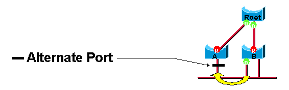
Section titled “Alternate and Backup Ports”These two port roles correspond to the blocking state of 802.1D. A blocked port is defined as not being the designated or root port. A blocked port receives a more useful BPDU than the one it sends out on its segment. Remember that a port needs to receive BPDUs in order to stay blocked. RSTP introduces these two roles for this purpose.
An alternate port receives more useful BPDUs from another bridge and is a port blocked. This is shown in this diagram:
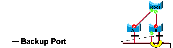
A backup port receives more useful BPDUs from the same bridge it is on and is a port blocked. This is shown in this diagram:
Topology Change Notifications
Section titled “Topology Change Notifications”When a port state change via a Blocked port transitioning to a Forwarding state, a topology change is triggered.
The following process occurs when a topology change is triggered:
- A non-edge port state changes from BLK -> FWD.
- The detecting bridge flushes its MAC address table except on the interface that received the TCN.
- For twice the hello-timer, the detecting bridge generates Configuration BPDUs with the TNC bit set, out all interfaces.
When a neighboring bridge receives the TCN notification, it begins the process from step 2.
Resources
Section titled “Resources”Cisco Whitepaper: https://www.cisco.com/c/en/us/support/docs/lan-switching/spanning-tree-protocol/24062-146.html